 ar
ar bg
bg hr
hr cs
cs da
da nl
nl fi
fi fr
fr de
de el
el hi
hi it
it ko
ko no
no pl
pl pt
pt ro
ro ru
ru es
es sv
sv tl
tl iw
iw id
id lv
lv lt
lt sr
sr sk
sk sl
sl uk
uk vi
vi et
et hu
hu th
th tr
tr fa
fa ms
ms hy
hy ka
ka ur
ur bn
bn mn
mn ta
ta kk
kk uz
uz ku
ku
load cell wire diagram
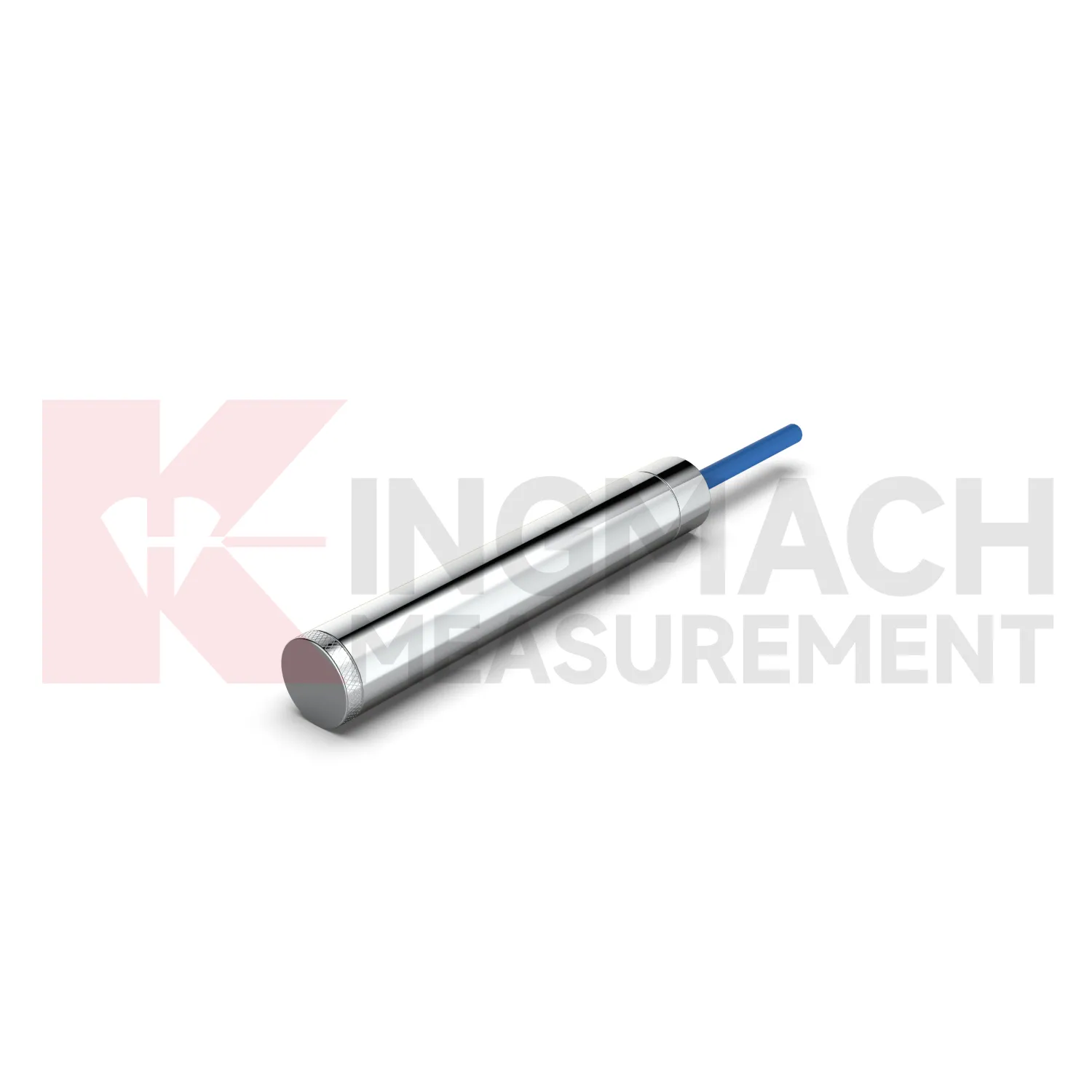
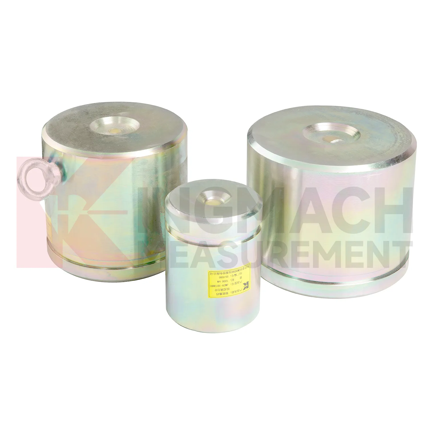
Kingmach load cell wire diagram covers more than one mechanical form, which matters because force does not enter every structure the same way. The solid load cell JMZX-35XXHAT is listed for 1000 kN to 10000 kN with 0.1 kN resolution and 0.5%FS precision. The same product file gives a -30°C to 80°C working temperature range, 20 to 50%F.S. range overload, and 300 to 400%F.S. failure overload. It also stores model, number, calibration coefficient, pressure value, zero parameter, and temperature correction data. These points make it better suited to compression load checks such as pile load testing, bridge pier support measurement, and heavy structural bearing work. The instrument is part of a larger Kingmach monitoring catalog that includes displacement, settlement, tilt, pressure, water level, and acquisition products. For procurement, the practical review should cover capacity margin, bearing surface geometry, calibration documents, expected temperature range, overload exposure, and whether the readings will be taken locally or fed into an automated system. Kingmach also presents the product family alongside project areas such as bridges, dams, tunnels, subways, slopes, buildings, subgrades, wind towers, and foundation pits. That makes the specification less abstract: each model can be matched to a known load path and a known field environment before ordering.
Application of load cell wire diagram
In pile load testing and bearing capacity verification, load cell wire diagram helps track applied force, load stages, unloading response, and residual behavior. The common problem is uncertainty around whether the applied load is centered and whether the recorded value matches the actual force passing through the test system. Kingmach solid load cells such as JMZX-35XXHAT list 1000 kN to 10000 kN ranges, 0.1 kN resolution, and 0.5%FS precision, with overload information listed as 20 to 50%F.S. range overload and 300 to 400%F.S. failure overload. These figures suit heavy test work when capacity margin must be checked before the sensor is installed. During the test, the record should include each loading step, hold time, unloading step, zero check, temperature, and any change to the bearing arrangement. Pairing the load record with settlement readings gives a clearer view of pile response. After the test, the documented calibration coefficient and instrument identity help keep the acceptance file defensible. Test reports should also record jack pressure, settlement response, load rate, hold duration, and any adjustment to the reaction system. These records help engineers identify whether an unusual load value came from the pile, the loading setup, or the measurement chain.
The future of load cell wire diagram
The next stage for load cell wire diagram in infrastructure monitoring is tighter integration with site data systems. Smart sensors already store model data, calibration coefficients, zero values, temperature readings, and measurement records on selected Kingmach products. The practical path is to connect that identity data with 4G, LoRa, wired acquisition, or 5G gateways, then place the force trend beside displacement, settlement, pore pressure, and rainfall in the same review screen. This matters because future warnings will be less about one limit value and more about patterns: force rising after excavation, anchor load falling after heavy rain, or bridge cable force drifting during seasonal temperature cycles. Digital twin models can use those readings when the sensor location, range, and calibration background are reliable. Standards and owner specifications for structural health monitoring are also becoming more data traceability focused, which favors instruments that can carry their own calibration identity and remain readable through long service periods.
Care & Maintenance of load cell wire diagram
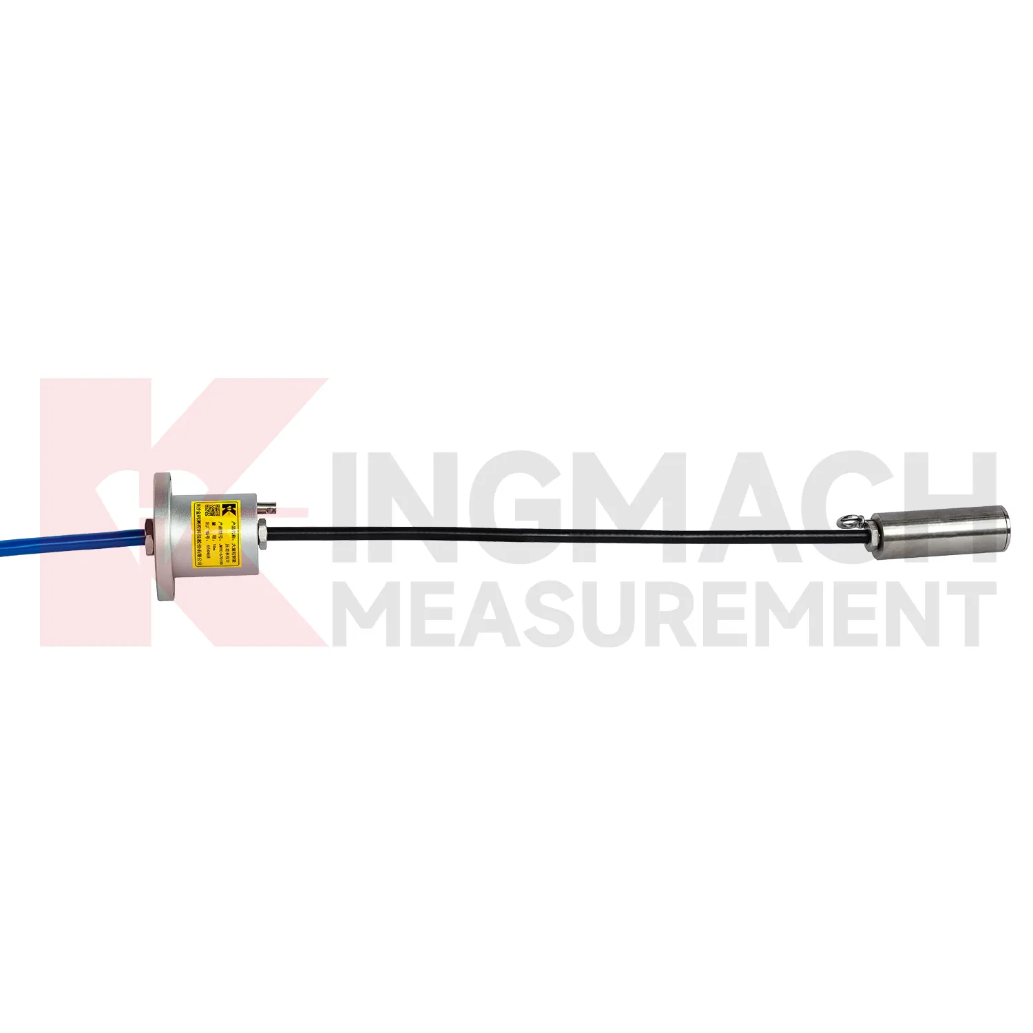
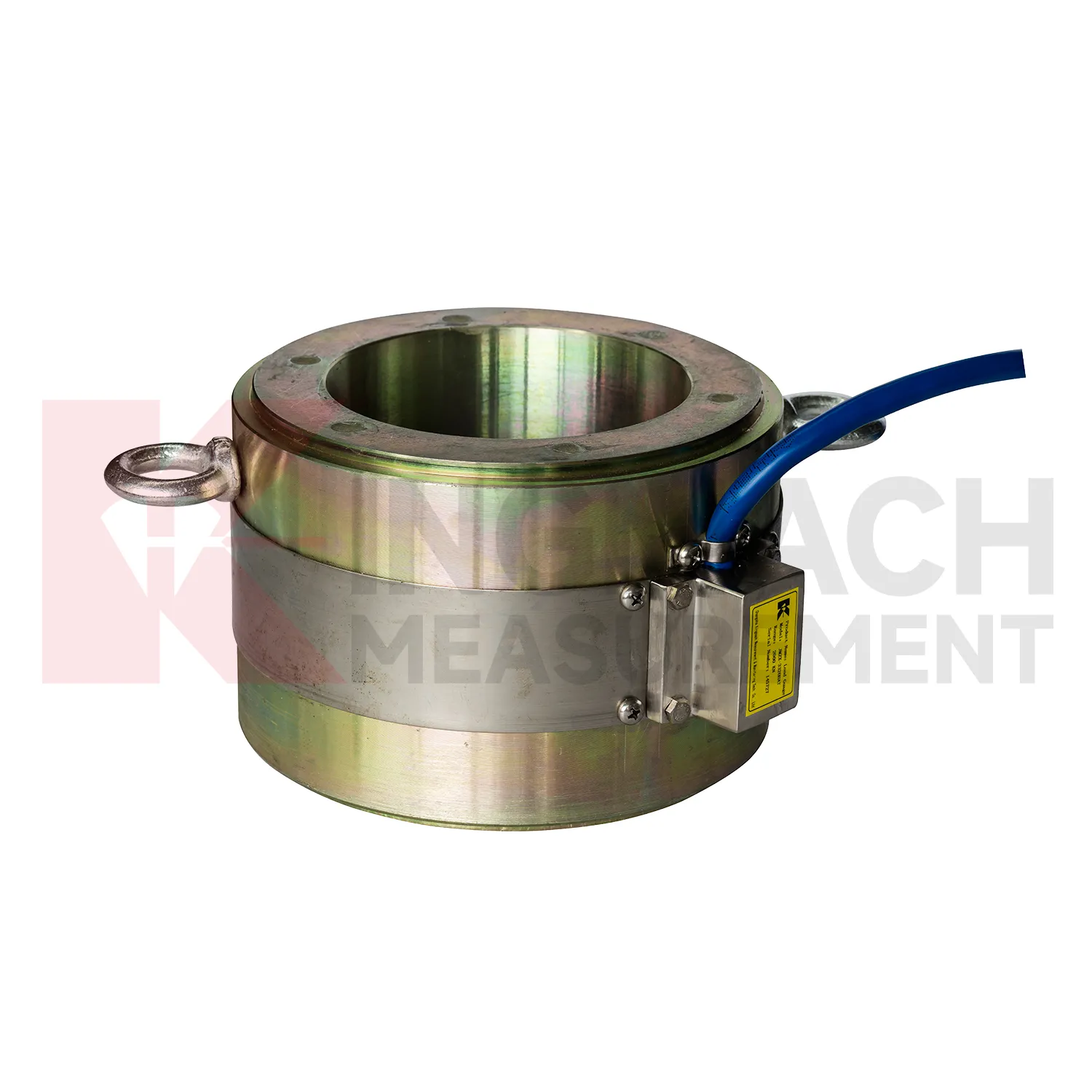
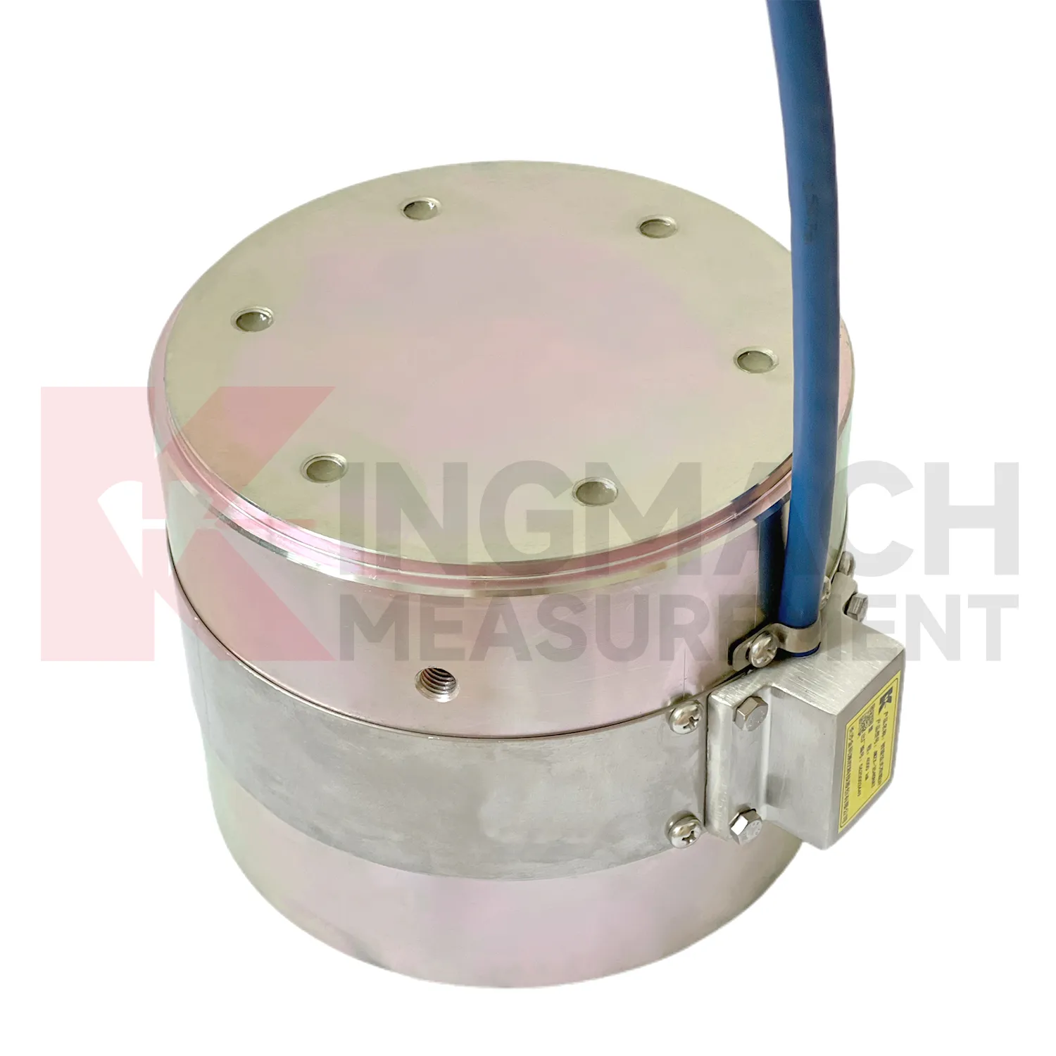
For load cell wire diagram used in bridge cable or anchor monitoring, maintenance should focus on the load path and the environment around the sensor. Hollow load cells list 500 kN to 8000 kN ranges, temperature correction, waterproof durability, and 800 stored measurement records on smart models. These features support long term observation, but they do not replace site checks. During installation, make sure the washer, bearing plate, anchor head, and sensor axis are properly seated. Record the first stable force after locking and keep the temperature reading with it. During operation, inspect cable protection, connector sealing, corrosion exposure, and any change near the anchor zone. Compare force records after seasonal temperature shifts, heavy traffic periods, maintenance work, or extreme weather. If one point changes while nearby points remain stable, check the bearing surface and wiring before treating the reading as structural behavior. A clean maintenance log helps separate sensor issues from real force redistribution.
Kingmach load cell wire diagram
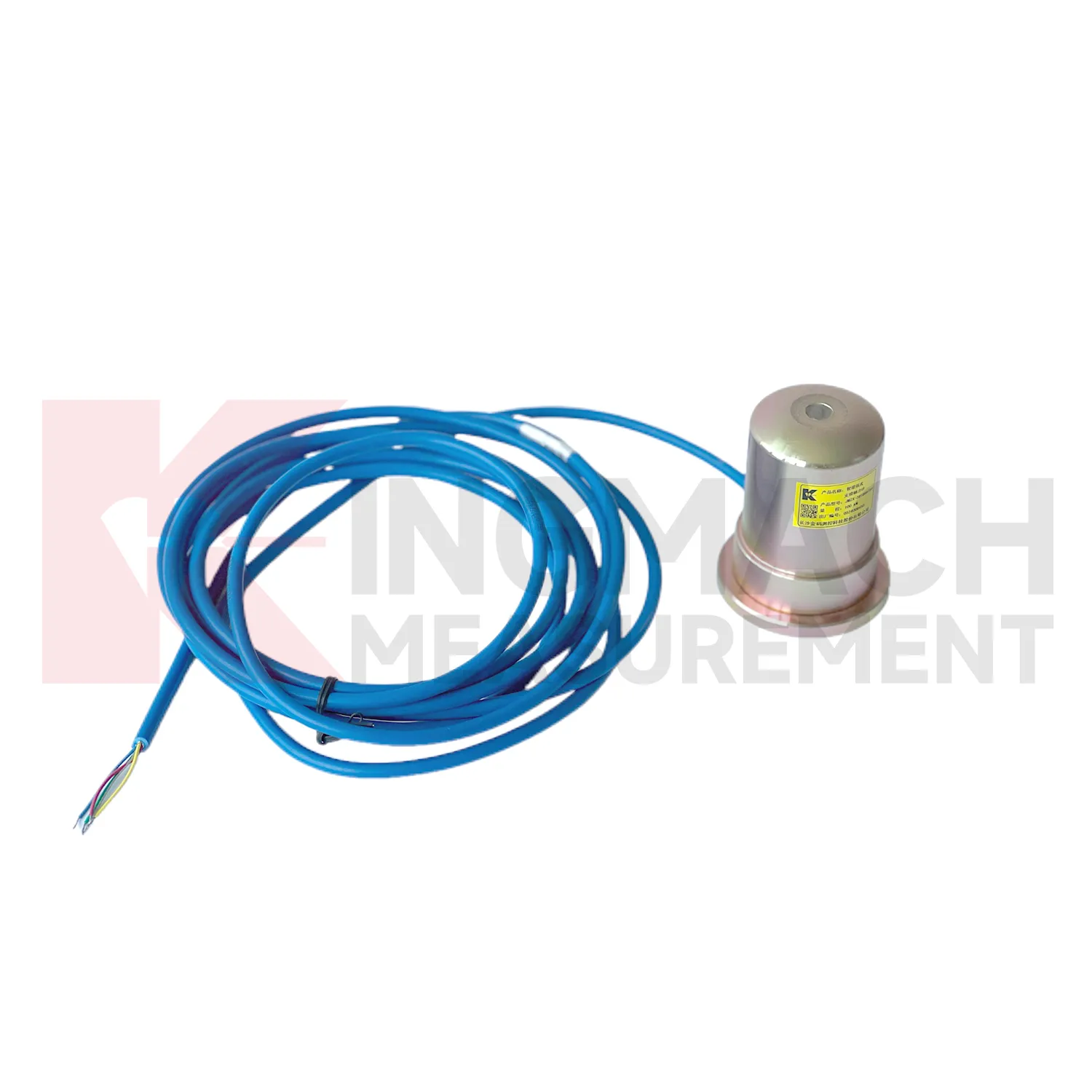
load cell wire diagram can be treated as a field witness for hidden force transfer in civil structures. Concrete, steel, soil, cable systems, and hydraulic loading may all look calm while the internal load path changes. Kingmach products in this category cover hollow load cells for anchors and cables, solid load cells for compression and pile testing, axial force meters for steel support loads, and earth pressure cells for contact pressure. Each type answers a different site question. Has the anchor lost tension? Is a pile test load centered? Is an excavation support taking more force after the next soil layer is removed? Is water pressure pushing the retaining structure harder after rain? The strongest monitoring records combine the sensor model, calibrated coefficient, zero value, temperature, reading time, and construction stage. That record gives owners a way to compare today with last week, last season, or the previous loading step, instead of relying on a single inspection note.
FAQ
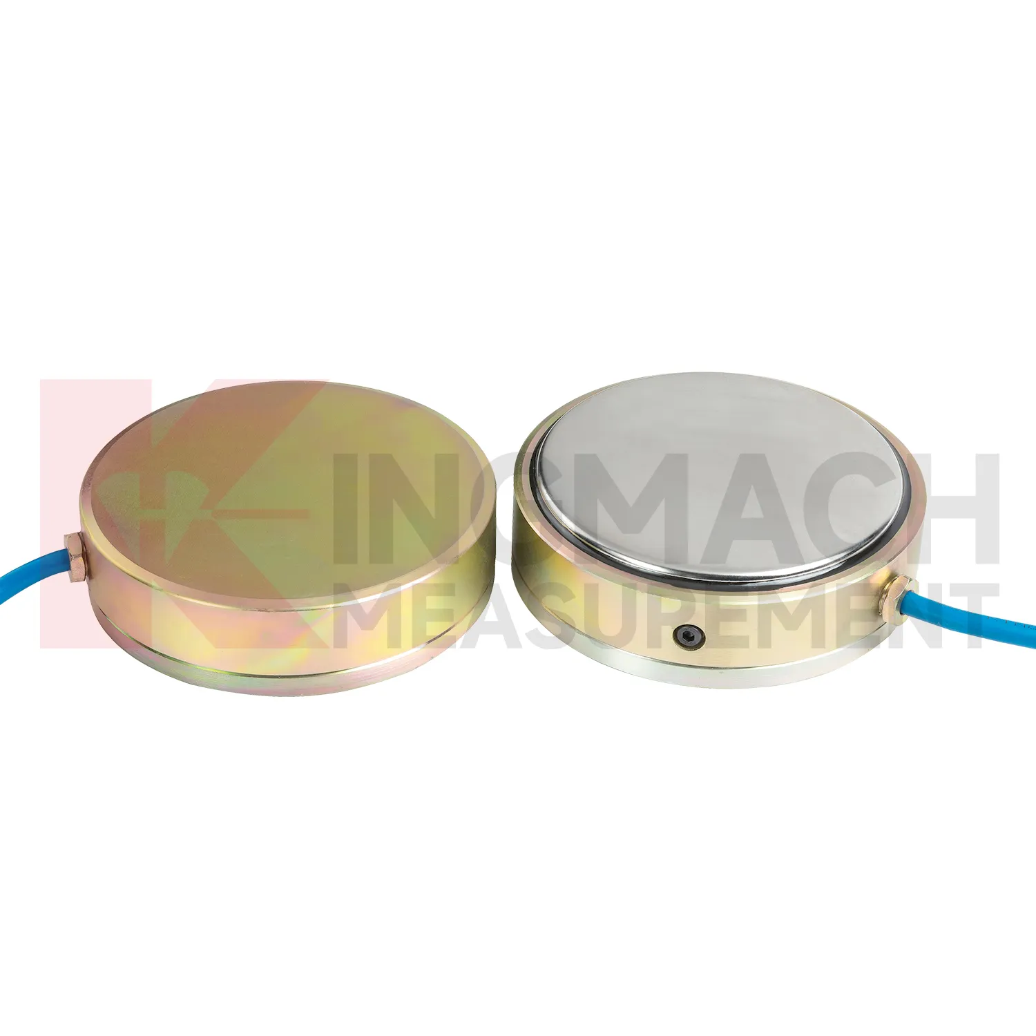
Q: Can load cell wire diagram be used for soil pressure or retaining wall pressure? A: Yes, pressure related models such as earth pressure cells are used where the measured value is contact pressure rather than direct member force. Q: What ranges are listed for Kingmach earth pressure cells? A: The JMZX-50XXAT/ATM family lists 0.3 MPa, 0.6 MPa, 1 MPa, 2 MPa, 4 MPa, 6 MPa, and 8 MPa ranges. Q: What accuracy and resolution are listed? A: The product file gives 0.001 MPa pressure resolution, 0.5%FS pressure accuracy, and ±0.5°C temperature accuracy. Q: Where are these readings useful? A: Foundation pits, dams, slopes, retaining walls, embankments, tunnels, and buried structures. Q: What maintenance issue is most common? A: Cable damage, water entry, channel confusion, and poor installation records cause many field doubts.
Reviews
Daniel Brown
Excellent environmental monitoring sensors. The data is consistent, and the system integrates smoothly with our existing setup.
Christopher Martinez
Very satisfied with the readouts & data loggers. User-friendly interface and supports multiple sensor inputs.
Latest Inquiries
To protect the privacy of our buyers, only public service email domains like Gmail, Yahoo, and MSN will be displayed. Additionally, only a limited portion of the inquiry content will be shown.
Mia***@gmail.comNetherlands
Dear team, we are interested in your readouts & data loggers compatible with multiple sensors. Do yo...
Olivia***@gmail.comUnited States
Hello, we are currently sourcing high-precision strain gauges and load cells for a bridge monitoring...