
 EN
EN
 ar
ar bg
bg hr
hr cs
cs da
da nl
nl fi
fi fr
fr de
de el
el hi
hi it
it ko
ko no
no pl
pl pt
pt ro
ro ru
ru es
es sv
sv tl
tl iw
iw id
id lv
lv lt
lt sr
sr sk
sk sl
sl uk
uk vi
vi et
et hu
hu th
th tr
tr fa
fa ms
ms hy
hy ka
ka ur
ur bn
bn mn
mn ta
ta kk
kk uz
uz ku
ku
load cell design
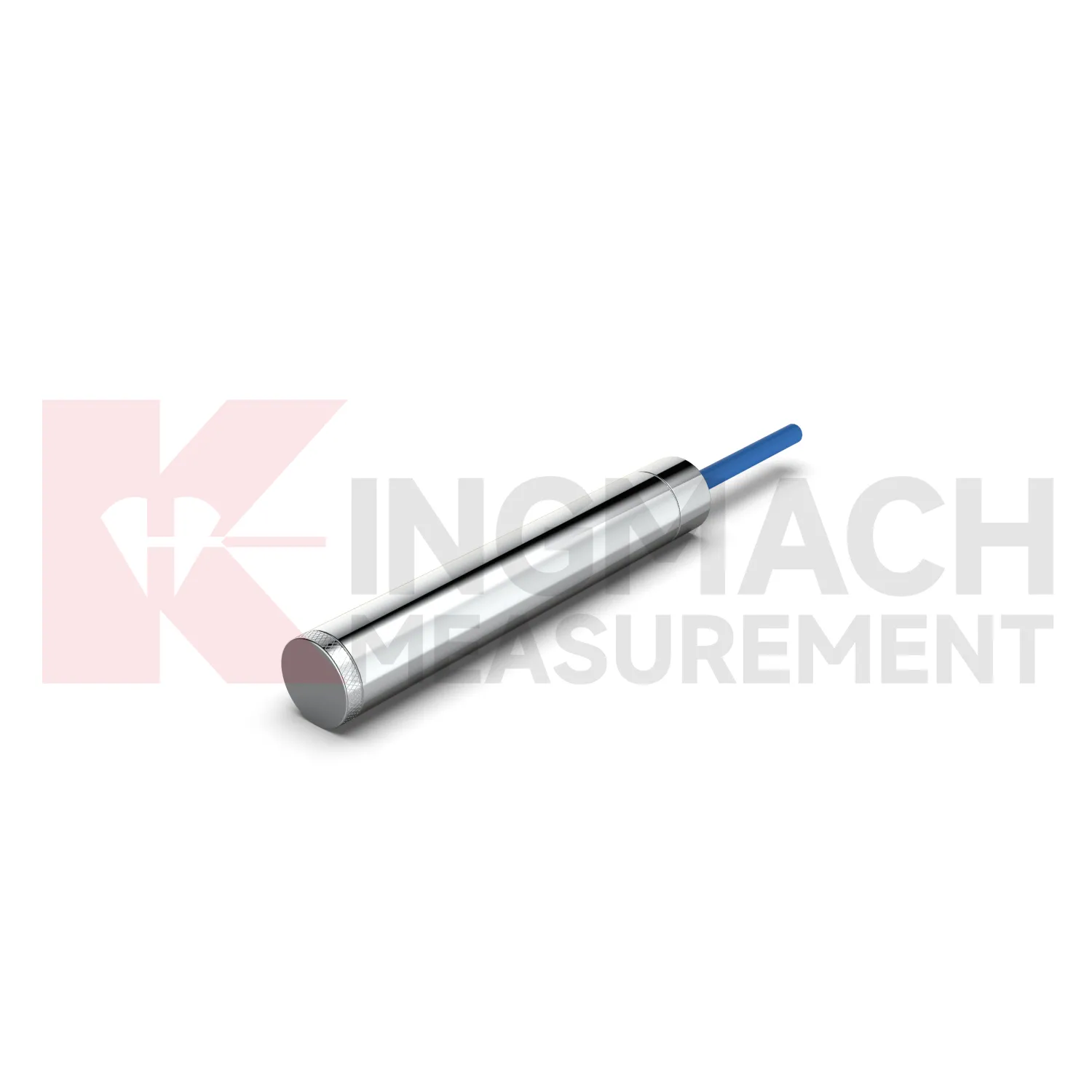
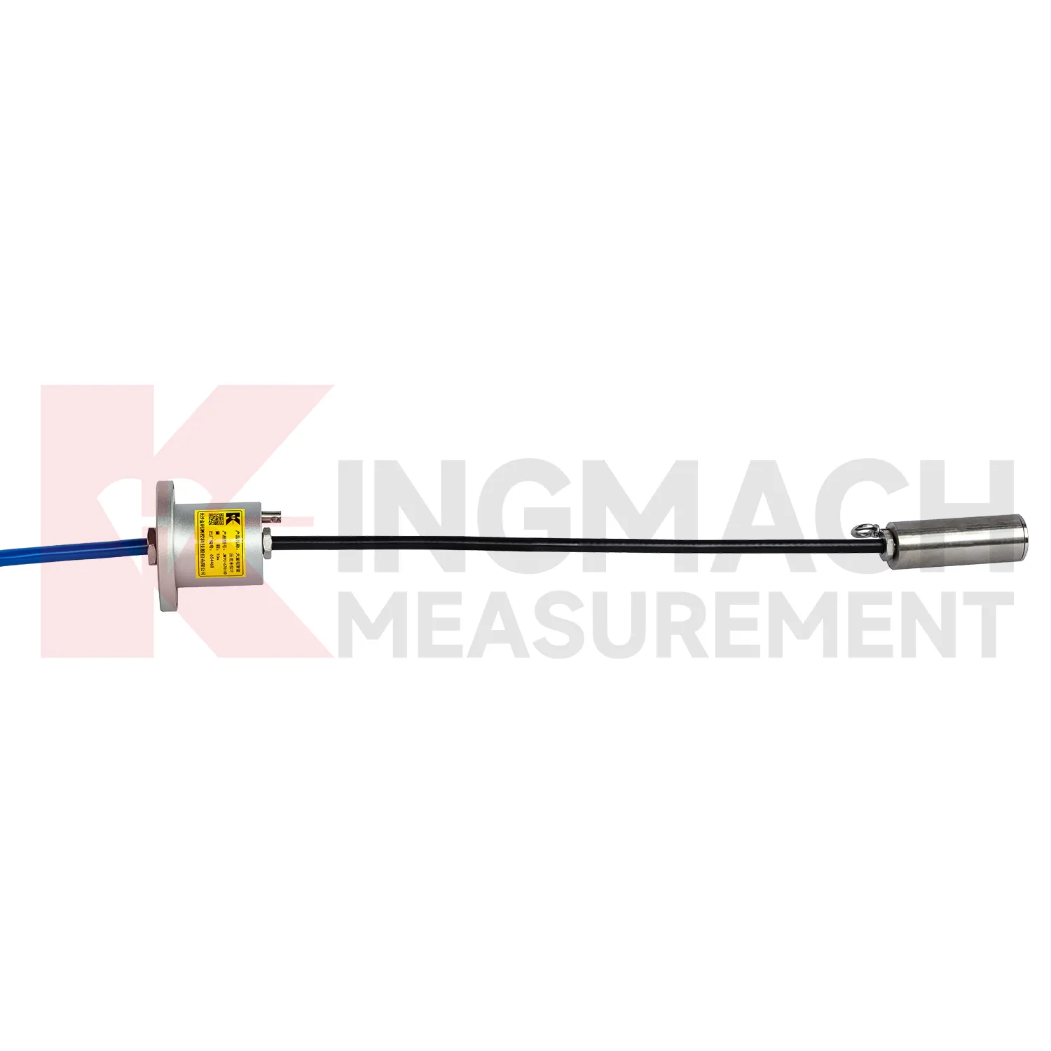
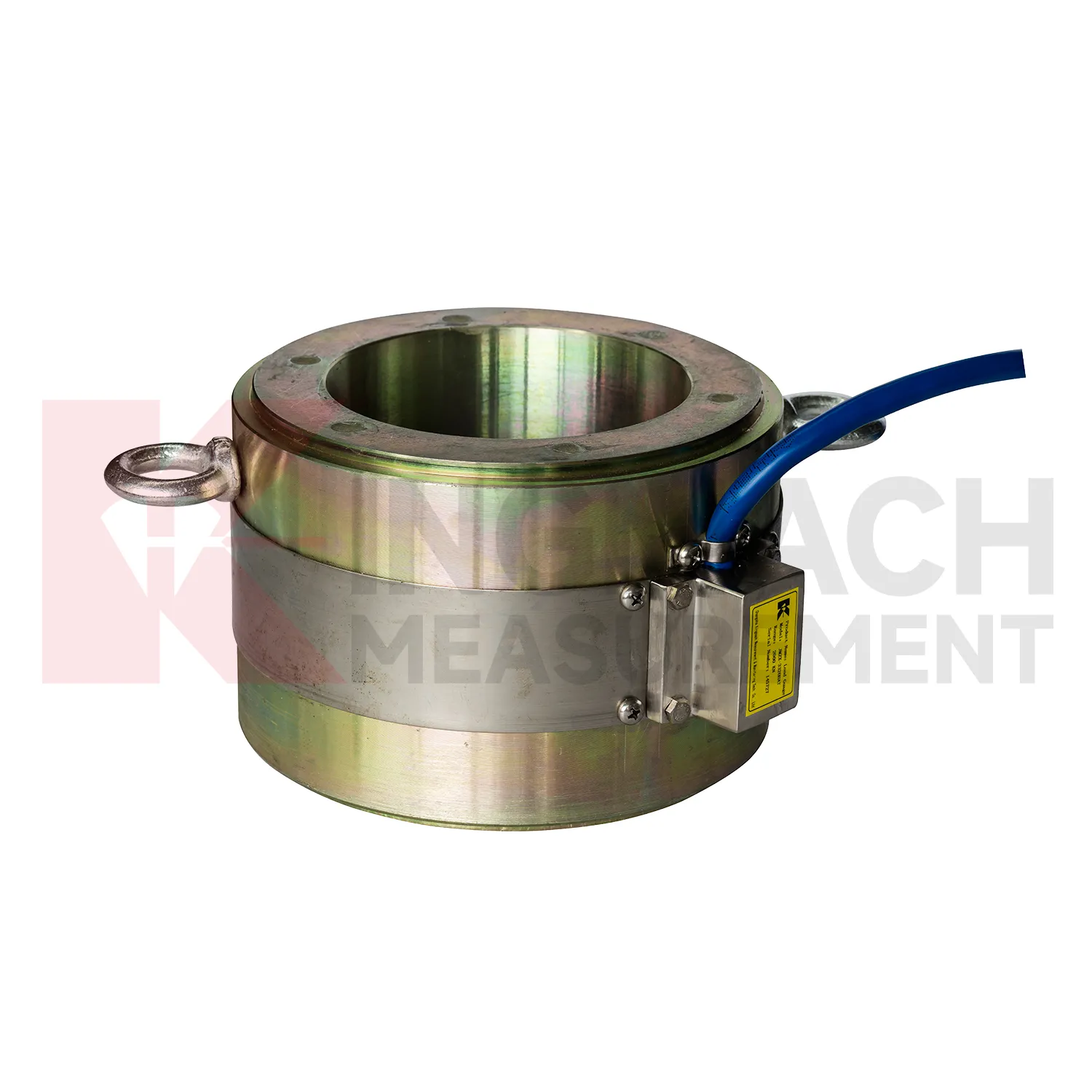
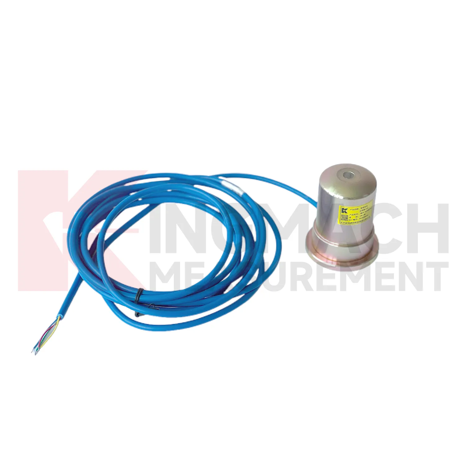
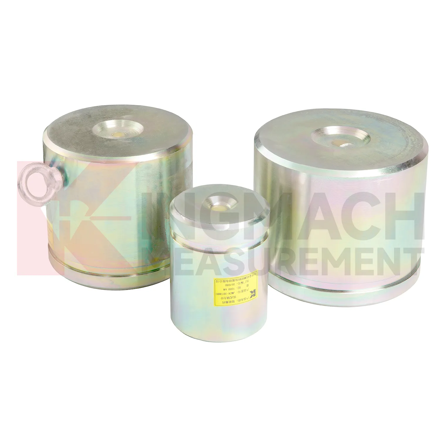
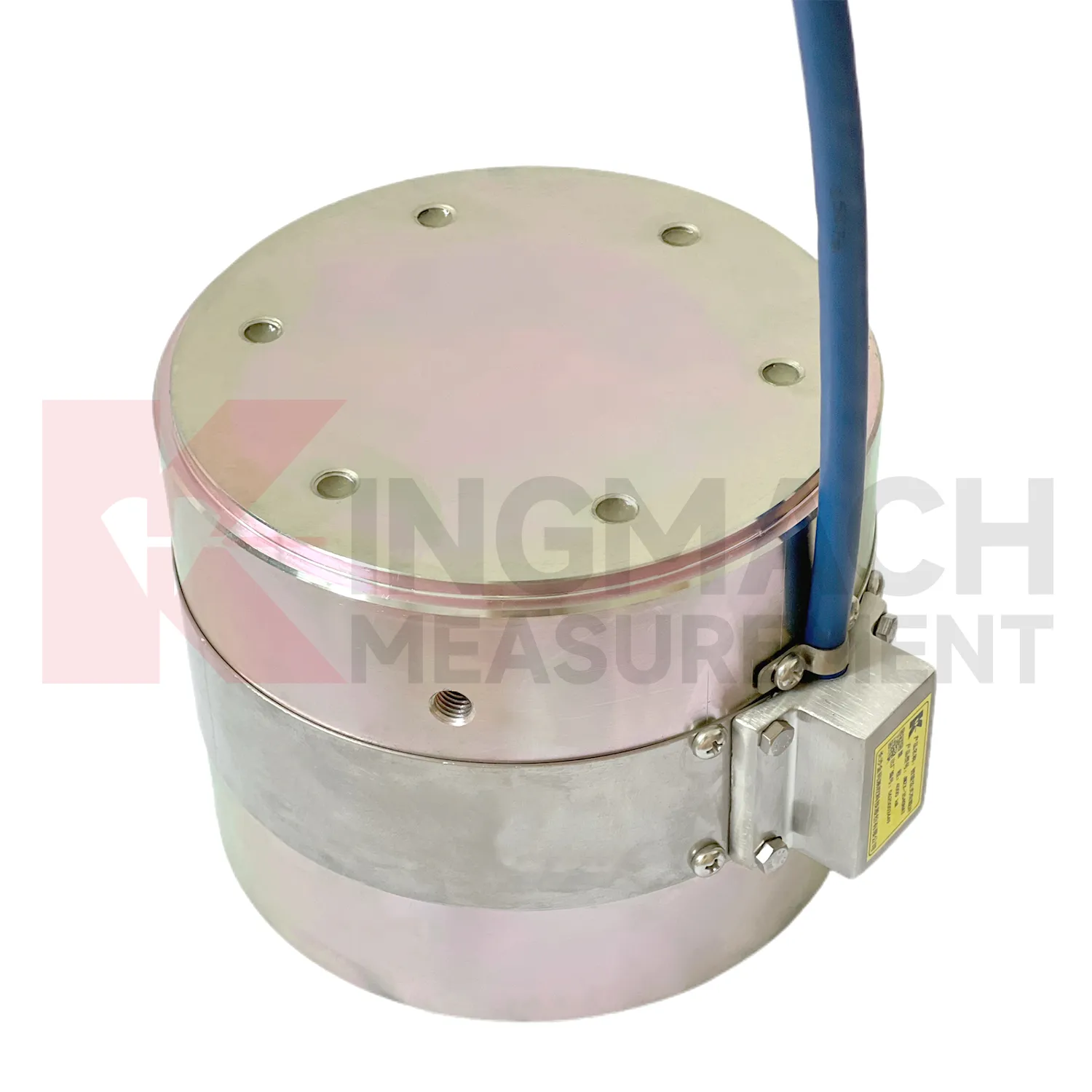
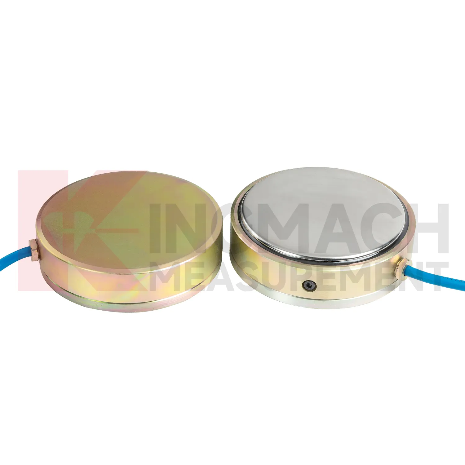
Kingmach load cell design descriptions should be read together with the data chain around the sensor. A hollow load cell can cover 500 kN to 8000 kN with a long service design, while the solid load cell line reaches 10000 kN with 0.5%FS precision. The axial force meter adds direct kN display and a 1 MPa waterproof rating for support load monitoring. Smart models include memory for calibration information, zero values, temperature data, and stored measurement records. These are not decorative features. They reduce uncertainty when many sensors are installed across a bridge, tunnel, foundation pit, dam, or rail project. Kingmach supplies readouts and data acquisition equipment, so a single instrument can be used for manual reading during installation and later connected to centralized monitoring if the owner requires it. The better specification path starts with the monitored member, expected load range, access condition, waterproof exposure, temperature swing, cable distance, and reporting method, then selects the model around those constraints. Kingmach's after-sales information also refers to warranty service, anti-static and shockproof packaging, and technical response support. Those points are useful in force monitoring because sensor damage, delivery handling, and setup questions can all affect whether the first readings are trusted.
Application of load cell design
In pile load testing and bearing capacity verification, load cell design helps track applied force, load stages, unloading response, and residual behavior. The common problem is uncertainty around whether the applied load is centered and whether the recorded value matches the actual force passing through the test system. Kingmach solid load cells such as JMZX-35XXHAT list 1000 kN to 10000 kN ranges, 0.1 kN resolution, and 0.5%FS precision, with overload information listed as 20 to 50%F.S. range overload and 300 to 400%F.S. failure overload. These figures suit heavy test work when capacity margin must be checked before the sensor is installed. During the test, the record should include each loading step, hold time, unloading step, zero check, temperature, and any change to the bearing arrangement. Pairing the load record with settlement readings gives a clearer view of pile response. After the test, the documented calibration coefficient and instrument identity help keep the acceptance file defensible. Test reports should also record jack pressure, settlement response, load rate, hold duration, and any adjustment to the reaction system. These records help engineers identify whether an unusual load value came from the pile, the loading setup, or the measurement chain.
The future of load cell design
Industrial and test bench use of load cell design will likely move toward automated verification. High capacity solid load cells with 0.5%FS precision and ranges up to 10000 kN can already support heavy compression tests, jack calibration work, and equipment checks. Future systems can connect these instruments to local software that records test stages, operator notes, temperature, overload events, and calibration status. That reduces the risk of a handwritten record being separated from the force data. Edge acquisition can also prevent common errors by warning when the zero point is unstable, the load rate is outside procedure, or the sensor range is being approached too quickly. Kingmach's smart memory features fit this direction because the sensor can carry identity and calibration background. The strongest future workflow will combine rugged hardware, automatic records, and simple review tools, so a test can be repeated months later with the same measurement basis. The same logic applies to factory tests and site acceptance.
Care & Maintenance of load cell design
For load cell design used in pile load testing, care begins before the first load step. Confirm that the selected solid load cell range, often between 1000 kN and 10000 kN on Kingmach listed models, exceeds the planned test load with proper margin. Check the 0.1 kN resolution, 0.5%FS precision, calibration certificate, bearing plate flatness, and centering arrangement. During the test, protect the cable from jack movement and keep the readout position safe from vibration and water. Record zero value, temperature, load stage, hold time, unloading stage, and any pause or adjustment. After the test, inspect the sensor for dents, side load marks, connector damage, and cable jacket cuts. Store the calibration coefficient with the test report, not only with the instrument box. If later readings appear inconsistent, compare them with jack pressure, settlement data, and loading procedure before blaming the sensor. Store the report with the test file.
Kingmach load cell design
load cell design often sits between design intent and field behavior. Drawings may state the expected force, but site loading can change when excavation sequence, concrete curing, traffic, reservoir level, grouting, or prestressing work changes. Kingmach supplies sensors and acquisition equipment for bridges, tunnels, dams, subways, slopes, foundations, railways, buildings, and hydropower projects. In these settings, the sensor helps reveal whether a member is carrying its share of the load or taking more than expected. The instrument must fit the force range, the bearing surface, the environmental exposure, and the data workflow. A high capacity sensor with poor installation records is still hard to trust. A moderate range sensor with clear calibration, stable zero, protected cable, and a clean reading plan can produce stronger evidence. For that reason, force monitoring should be planned alongside installation details, not added after the site has already become crowded. This is especially useful when the monitored point becomes hidden after the next work stage.
FAQ
Q: What does load cell design do in a foundation pit or tunnel? A: It measures axial force in steel supports, anchor load, or pressure change as excavation and support stages progress. Q: Which Kingmach model fits steel support axial force? A: The JMZX-38XXHAT axial force meter is listed from 200 kN to 3000 kN, with 0.1 kN or 1 kN sensitivity and 0.5%FS accuracy. Q: Is it suitable for wet underground sites? A: The axial force meter lists a 1 MPa waterproof rating, but connector sealing and cable routing still need inspection. Q: Why is direct kN display useful? A: It reduces confusion because teams can read axial force directly instead of converting vibrating wire frequency on site. Q: What should trigger extra checks? A: Excavation step changes, rainfall, dewatering, support adjustment, sudden force jumps, or unstable channels.
Reviews
David Wilson
We purchased displacement transducers and settlement sensors, and the quality exceeded our expectations. Easy installation and reliable performance.
Matthew Garcia
Instrumentation cables are durable and perform well even in harsh environments. Will definitely order again.
Latest Inquiries
To protect the privacy of our buyers, only public service email domains like Gmail, Yahoo, and MSN will be displayed. Additionally, only a limited portion of the inquiry content will be shown.
Amelia***@gmail.comSingapore
Hello, I am looking for visualization software for monitoring system data analysis. Please let me kn...
Olivia***@gmail.comUnited States
Hello, we are currently sourcing high-precision strain gauges and load cells for a bridge monitoring...
Related product categories
- load cell zero balance
- load cell connection diagram
- load cell recalibration
- load cell testing
- load cell wiring schematic
- calibration load cells
- calibration of load cell theory
- load cell failure
- load cell technology
- strain gauge load cell wiring
- diagram 4 wire load cell wire connection
- load cell accuracy calculation